Lesson 31 - Bindings between shapes
In Lesson 23 - Mindmap, we only focused on the layout algorithms for nodes and edges, without diving into interactions such as moving edges when nodes are moved. Similarly, in Lesson 25 - Drawing arrows, the properties of lines and arrows did not include binding information. In this lesson, we will complete this functionality.
Data structure
Linear elements in excalidraw
In Excalidraw, connection lines (such as arrows) are represented in the data model as ExcalidrawLinearElement, which adds connection-related fields:
export declare type PointBinding = {
    elementId: ExcalidrawBindableElement['id'];
    focus: number;
    gap: number;
};
export declare type ExcalidrawLinearElement = _ExcalidrawElementBase &
    Readonly<{
        type: 'line' | 'arrow';
        points: readonly Point[];
        lastCommittedPoint: Point | null;
        startBinding: PointBinding | null;
        endBinding: PointBinding | null;
        startArrowhead: Arrowhead | null;
        endArrowhead: Arrowhead | null;
    }>;
As shown above, each arrow has optional startBinding and endBinding fields, which exist at a different semantic level than points. The former represents semantic constraints, while the latter points represents geometric representation. When both exist simultaneously, points needs to be recalculated. Additionally, there are start and end arrow styles (startArrowhead/endArrowhead). The elementId in PointBinding points to the connected shape (bindable elements such as rectangles, ellipses, text, images, etc.), while focus and gap are used to locate the connection point (a floating-point index and offset distance). For example, below is an example of an arrow element in JSON:
{
  "type": "arrow",
  // ... other properties omitted ...
  "startBinding": {
    "elementId": "xw25sQBsbd2mecyjTrYHA",
    "focus": -0.0227,
    "gap": 15.6812
  },
  "endBinding": null,
  "points": [[0,0],[0,109]],
  "startArrowhead": null,
  "endArrowhead": null
}
In this example, the arrow's startBinding points to a shape with ID "xw25sQBsbd2mecyjTrYHA", and focus and gap define the connection position starting from that shape's boundary.
At the same time, each bound shape (such as a rectangle or ellipse) has a boundElements list in its basic data structure, used to record all arrows or text elements connected to it. This field type is typically { id: ExcalidrawLinearElement["id"]; type: "arrow"|"text"; }[] | null. In other words, the connection between arrows and shapes is maintained bidirectionally: arrows record the target element ID they bind to, and target elements record the arrow IDs pointing to them.
Bindings in tldraw
In tldraw, "connection lines" themselves are also shapes (default is arrow shape), and their connection relationships are represented through Binding objects. Each binding record exists separately in storage, representing the association between two shapes. For arrow connections, the TLArrowBinding type is used, which is a specialization of TLBaseBinding<'arrow',TLArrowBindingProps>. A typical arrow binding record example is as follows:
{
  id: 'binding:abc123',
  typeName: 'binding',
  type: 'arrow',           // Binding type is arrow
  fromId: 'shape:arrow1',  // Arrow shape ID (arrow shape departure end)
  toId:   'shape:rect1',   // Target shape ID (shape the arrow points to)
  props: {
    terminal: 'end',       // Which end of the arrow to bind to (start or end)
    normalizedAnchor: { x: 0.5, y: 0.5 }, // Normalized anchor point on target shape
    isExact: false,        // Whether arrow enters inside target shape
    isPrecise: true,       // Whether to use anchor point precisely, otherwise use shape center
    snap: 'edge',          // Snap mode (such as edge snapping)
  },
  meta: {}
}
Here, the fromId/toId fields associate arrows with targets through shape IDs, and props stores connection details (such as anchor points, alignment options, etc.)
antv/g6
Connection relationships are logical, not geometric, and paths are calculated through type and edge routing algorithms:
interface EdgeConfig {
    id?: string;
    source: string; // Source node ID
    target: string; // Target node ID

    sourceAnchor?: number; // Source node anchor index
    targetAnchor?: number; // Target node anchor index

    type?: string; // line / polyline / cubic / loop ...
    style?: ShapeStyle;
}
Anchors are declared on nodes, with normalized coordinates:
anchorPoints: [
    [0.5, 0], // top
    [1, 0.5], // right
    [0.5, 1], // bottom
    [0, 0.5], // left
];
Anchor indices are used on edges, very similar to tldraw's normalizedAnchor, but G6 places the anchor definition authority on nodes:
{
    source: 'nodeA',
    target: 'nodeB',
    sourceAnchor: 1,
    targetAnchor: 3,
}
mxGraph
mxGraph has a complete connection constraint system, defined on node shapes, representing allowed connection points:
class mxConnectionConstraint {
    point: mxPoint | null; // (0.5, 0) = top center (1, 0.5) = right center
    perimeter: boolean; // Indicates projection along shape boundary
}
JSON Canvas Spec
Obsidian publishes the JSON Canvas Spec, which is structurally similar to antv/g6: the top level stores arrays of nodes and edges:
{
    "nodes": [],
    "edges": []
}
Edges look like the following — they carry no geometry, only logical connection:
{
    "id": "f67890123456789a",
    "fromNode": "6f0ad84f44ce9c17",
    "toNode": "a1b2c3d4e5f67890"
}
Our design
On the schema we lean more on mxGraph’s approach. Logical relationships on an edge are expressed with fromId and toId, so we do not need geometric fields such as x1/y1. An arrow connecting rect-1 and rect-2 is declared like this:
const edge1 = {
    id: 'line-1',
    type: 'line',
    fromId: 'rect-1',
    toId: 'rect-2',
    stroke: 'black',
    strokeWidth: 10,
    markerEnd: 'line',
};
Constraints live on the node, similar to mxConnectionConstraint:
interface ConstraintAttributes {
    /**
     * Normalized point, relative to bounding box top-left.
     */
    point: [number, number];
    /**
     * Use perimeter.
     */
    perimeter: boolean;
    name?: string;
    dx?: number;
    dy?: number;
}
Similar to Lesson 18 - Defining Parent-Child Components, we can implement bidirectional binding relationships:
class Binding {
    @field.ref declare from: Entity;
    @field.ref declare to: Entity;
}

class Binded {
    @field.backrefs(Binding, 'from') declare fromBindings: Entity[];
    @field.backrefs(Binding, 'to') declare toBindings: Entity[];
}
Special case
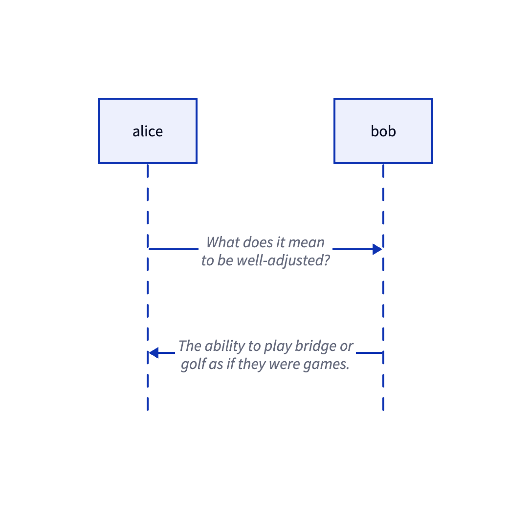
In the next lesson, we will encounter a special case where fromId/toId may be null, as indicated by the dashed lines in the sequence diagram below, fromId: 'alice', toId: undefined
We introduce a new component that records a relationship with only one associated node:
/**
 * Edge with only one end attached to a shape; the other end is fixed by `sourcePoint` / `targetPoint`.
 * `attached` is the entity on the connected side; `sourceIsAttached === 1` means the connection is on the source (`fromId`) side.
 */
class PartialBinding {
    @field.ref declare attached: Entity;
    /** 1 = source (from) side attached to node, 0 = target (to) side */
    @field.int32 declare sourceIsAttached: number;
}
Auto update
When the position of connected shapes changes, the paths of bound edges need to be recalculated. We can query all shapes that have the Binded component, monitor their bounding box changes, and update bound edges at that time:
class RenderBindings extends System {
    private readonly boundeds = this.query(
        (q) => q.with(Binded).changed.with(ComputedBounds).trackWrites,
    );

    execute() {
        const bindingsToUpdate = new Set<Entity>();
        this.boundeds.changed.forEach((entity) => {
            const { fromBindings, toBindings } = entity.read(Binded);
            [...fromBindings, ...toBindings].forEach((binding) => {
                bindingsToUpdate.add(binding);
            });
        });
        // Recalculate paths of bound edges and render
    }
}
In the example below, you can try dragging nodes, and edges will recalculate paths and redraw:
Currently, the start and end points of edges are the bounding box centers of connected shapes, consistent with the effect when isPrecise equals false in tldraw, indicating imprecise binding. In most cases, we want arrows not to pass through the connected shapes, but to elegantly dock at the shape edges.
Perimeter algorithm
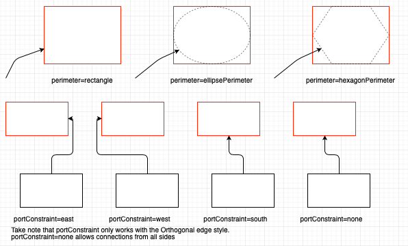
For shape boundaries, drawio provides the perimeter property, changing it affects connections. For details, see: Change the shape perimeter
// Note: generally next is passed as "the other center point", orthogonal is usually false
var pointA = graph.view.getPerimeterPoint(stateA, centerB, false, 0);
var pointB = graph.view.getPerimeterPoint(stateB, centerA, false, 0);
Rectangle perimeter algorithm
The rectangle perimeter algorithm is the most commonly used. In the following implementation, vertex is the source node, and next is the bounding box center of the target node. First, draw a line from the centers of the source and target node bounding boxes, then determine which edge of the source node bounding box the target point is closer to. The two diagonals of the bounding box divide the plane into four regions. The range of the left boundary is the region outside alpha < -pi + t || alpha > pi - t in the code):
function rectanglePerimeter(
    vertex: SerializedNode,
    next: IPointData,
    orthogonal: boolean,
): IPointData {
    const { x, y, width, height } = vertex;
    const cx = x + width / 2; // Source node center
    const cy = y + height / 2;
    const dx = next.x - cx;
    const dy = next.y - cy;
    const alpha = Math.atan2(dy, dx); // Slope of line from source node center to target node center
    const p: IPointData = { x: 0, y: 0 };
    const pi = Math.PI;
    const pi2 = Math.PI / 2;
    const beta = pi2 - alpha;
    const t = Math.atan2(height, width); // Diagonals divide into four regions
    if (alpha < -pi + t || alpha > pi - t) {
        // Intersects with left edge
        p.x = x;
        p.y = cy - (width * Math.tan(alpha)) / 2; // Calculate intersection point
    }
    // Other three edges omitted
    return p;
}
Finally, calculate the intersection point of the line with that edge as the departure point of the final line. For example, when we determine that the line will pass through the "left edge":
- Determine
coordinate: Since it's the left edge, the coordinate of the intersection point must equal the left boundary value of the rectangle, vertex.x. - Calculate
offset: - The horizontal distance from center to left edge is
width / 2. - Use the tangent formula:
. - On the left side,
. - So the vertical offset
.
- The horizontal distance from center to left edge is
- Final coordinate:
p.y = cy + Δy, which iscy - (width * Math.tan(alpha)) / 2in the code.
draw.io also provides another option orthogonal, which means the calculated line needs to be orthogonally aligned (i.e., aligned with the x or y axis), and the line only considers horizontal or vertical extension. In this case, the other center point cannot be used as a reference:
if (orthogonal) {
    if (next.x >= x && next.x <= x + width) {
        p.x = next.x;
    } else if (next.y >= y && next.y <= y + height) {
        p.y = next.y;
    }
    if (next.x < x) {
        p.x = x;
    } else if (next.x > x + width) {
        p.x = x + width;
    }
    if (next.y < y) {
        p.y = y;
    } else if (next.y > y + height) {
        p.y = y + height;
    }
}
Ellipse perimeter algorithm
For ellipse nodes, we need to calculate the intersection point of the line with it:
const d = dy / dx;
const h = cy - d * cx;
const e = a * a * d * d + b * b;
const f = -2 * cx * e;
const g = a * a * d * d * cx * cx + b * b * cx * cx - a * a * b * b;
const det = Math.sqrt(f * f - 4 * e * g);

const xout1 = (-f + det) / (2 * e);
const xout2 = (-f - det) / (2 * e);
const yout1 = d * xout1 + h;
const yout2 = d * xout2 + h;
const dist1 = Math.sqrt(Math.pow(xout1 - px, 2) + Math.pow(yout1 - py, 2));
const dist2 = Math.sqrt(Math.pow(xout2 - px, 2) + Math.pow(yout2 - py, 2));

let xout = 0;
let yout = 0;
if (dist1 < dist2) {
    xout = xout1;
    yout = yout1;
} else {
    xout = xout2;
    yout = yout2;
}
return { x: xout, y: yout };
The line passes through the center
- Slope
- Intercept
Substitute the line equation into the ellipse standard equation:
Expand and rearrange into a quadratic equation in
: Quadratic coefficient : Linear coefficient : Constant term
Quadratic formula: Use the discriminant next (dist1 and dist2), and selects the closest point.
Constraint
At this point, we have implemented logical connections on edges using only fromId and toId. The connection points for edges and nodes are floating, referred to as FloatingTerminalPoint in mxGraph. However, sometimes we want edges to depart from a fixed position on a node and enter from a fixed position on the connected shape, termed FixedTerminalPoint in mxGraph. In such cases, we need to define constraints, splitting the process into separate parts for nodes and edges.
Constraint on node
Node constraints define where and how connections can be made. They are not “points” but rule objects, defined in mxGraph as follows:
class mxConnectionConstraint {
    point: mxPoint | null; // Normalized coordinates (0~1)
    perimeter: boolean; // Whether to project onto the boundary
    name?: string; // Optional port name
}
In the accompanying draw.io editor, we can see numerous “blue connection points” on the diagram. These are defined by overriding the constraints on the diagram:
mxRectangleShape.prototype.getConstraints = function (style) {
    return [
        new mxConnectionConstraint(new mxPoint(0.5, 0), true), // top
        new mxConnectionConstraint(new mxPoint(1, 0.5), true), // right
        new mxConnectionConstraint(new mxPoint(0.5, 1), true), // bottom
        new mxConnectionConstraint(new mxPoint(0, 0.5), true), // left
    ];
};
Our constraints are defined as follows: A set of constraints can be declared on a node:
export interface ConstraintAttributes {
    x?: number;
    y?: number;
    perimeter?: boolean;
    dx?: number;
    dy?: number;
}

export interface BindedAttributes {
    constraints: ConstraintAttributes[];
}
Retrieve candidate constraints, select the nearest constraint, and convert the constraint into a geometric point. If projection onto the boundary is required, proceed to the boundary algorithm computation logic introduced in the previous section.
Constraint on edge
You also need to define which anchor point of the node the edge will enter or exit from. During interaction, this corresponds to dragging the edge's endpoint onto the node's anchor point. At this point, entryX/entryY must copy the x/y field from the anchor point constraint:
interface BindingAttributes {
    fromId: string;
    toId: string;
    orthogonal: boolean;
    exitX: number;
    exitY: number;
    exitPerimeter: boolean;
    exitDx: number;
    exitDy: number;
    entryX: number;
    entryY: number;
    entryPerimeter: boolean;
    entryDx: number;
    entryDy: number;
}
In the following example, we have defined anchor points [1, 0] and [0, 1] on the gray and green rectangles respectively.
Routing rules
mxGraph uses EdgeStyle functions to implement routing rules, which are responsible for:
- Automatically selecting exit directions
- Inserting waypoints
- Avoiding node bounding boxes
- Calculating orthogonal/right-angle paths
| Connector | Features | Use Cases |
|---|---|---|
| OrthConnector | Automatically generates orthogonal edges with complex constraint support | Flowcharts, organizational charts, and other auto-layout scenarios |
| SegmentConnector | Supports user-defined control points, flexible and interactive | When users need to manually adjust orthogonal edge paths |
| ElbowConnector | Single L-shaped turning point | Simple 2-segment paths (e.g., breadcrumb navigation) |
| SideToSide | Horizontal direction priority connection | When source and target nodes are horizontally distributed |
| TopToBottom | Vertical direction priority connection | When source and target nodes are vertically distributed |
| EntityRelation | Database relationship diagram specific, generates flexible paths | Database ER diagrams, bidirectional relationships |
| Loop | Implements self-loop connections | Self-loop relationships in state diagrams or automaton charts |
OrthConnector
OrthConnector is the most common routing algorithm, with the core objective of creating a path between the source and destination nodes that consists solely of horizontal and vertical line segments, avoiding diagonal lines. The specific steps are as follows:
- Determine the exit/entry direction for the source and destination
- Search for predefined routing patterns based on direction combinations
- Apply routing patterns to generate a sequence of turning points
- Handle obstacle avoidance and optimization
┌──────┐        ┌──────┐
│ Node │ ─┐     │ Node │
└──────┘  └────▶└──────┘
Preferred port selections
First, consider the case with no port constraints. The initial step is to determine the target's quadrant position relative to the source. By comparing the geometric center points of both, we obtain:
// 0 | 1
// -----
// 3 | 2

let dx = sourceCenX - targetCenX;
let dy = sourceCenY - targetCenY;
let quad = 0;
if (dx < 0) {
    if (dy < 0) {
        quad = 2;
    } else {
        quad = 1;
    }
}
// Other circumstances omitted.
Next comes the most complex part: determining which direction edges should depart from the source node and enter the destination node.
First, calculate the distance between nodes:
        sourceTopDist
             ↑
    [Source] |
             ↓
        sourceBottomDist
             ↑
             | [Target]

sourceLeftDist ← [Source] → sourceRightDist → [Target]
Then determine the preferred direction using a strategy that favors the direction with greater available space:
- If the distance to the left ≥ the distance to the right, the source node prefers to move west (left).
- If the distance to the top ≥ the distance to the bottom, the source node prefers to move north (up).
- The target node's preferred direction is the opposite direction of the source node.
var dirPref = [];
var horPref = [];
var vertPref = [];

horPref[0] =
    sourceLeftDist >= sourceRightDist
        ? mxConstants.DIRECTION_MASK_WEST
        : mxConstants.DIRECTION_MASK_EAST;
vertPref[0] =
    sourceTopDist >= sourceBottomDist
        ? mxConstants.DIRECTION_MASK_NORTH
        : mxConstants.DIRECTION_MASK_SOUTH;

horPref[1] = mxUtils.reversePortConstraints(horPref[0]);
vertPref[1] = mxUtils.reversePortConstraints(vertPref[0]);

var preferredHorizDist =
    sourceLeftDist >= sourceRightDist ? sourceLeftDist : sourceRightDist;
var preferredVertDist =
    sourceTopDist >= sourceBottomDist ? sourceTopDist : sourceBottomDist;
Choose route patterns
Based on the directional indices of the source and destination, select a route pattern from the predefined routePatterns to ensure quality, encoded using a bitmask:
- Low 4 bits: Direction (1=West, 2=North, 4=East, 8=South)
- Bits 5-8: Which side of the edge
- Bit 9: Whether to use the center point
- Bit 10: Whether to associate with the source node
- Bit 11: Whether to associate with the destination node
routePatterns: [
    [ [ 513, 2308, 2081, 2562 ], [ 513, 1090, 514, 2184, 2114, 2561 ],
        [ 513, 1090, 514, 2564, 2184, 2562 ],
        [ 513, 2308, 2561, 1090, 514, 2568, 2308 ] ],
    // ... more patterns
],
Generate waypoints
Iterate through the routing patterns and generate actual path points based on direction.
for (var i = 0; i < routePattern.length; i++)
{
    var nextDirection = routePattern[i] & 0xF;

    // Rotate the index of this direction by the quad
    var directionIndex = nextDirection == mxConstants.DIRECTION_MASK_EAST ? 3
            : nextDirection;

    directionIndex += quad;

    if (directionIndex > 4)
    {
        directionIndex -= 4;
    }
Finally, simplify adjacent path points that lie very close together. For this we continue to use simplify-js, as in Lesson 12 - Simplifying polyline.
SegmentConnector
OrthConnector leans toward automatic routing. When the user explicitly specifies control points controlHints, SegmentConnector turns those hints into waypoints that must be passed through or aligned to, and the resulting polyline is largely built around these hints—so it is more predictable and consistent for interactive editing.
LoopConnector
When the start and end coincide, we need a self-loop.
Connector line style
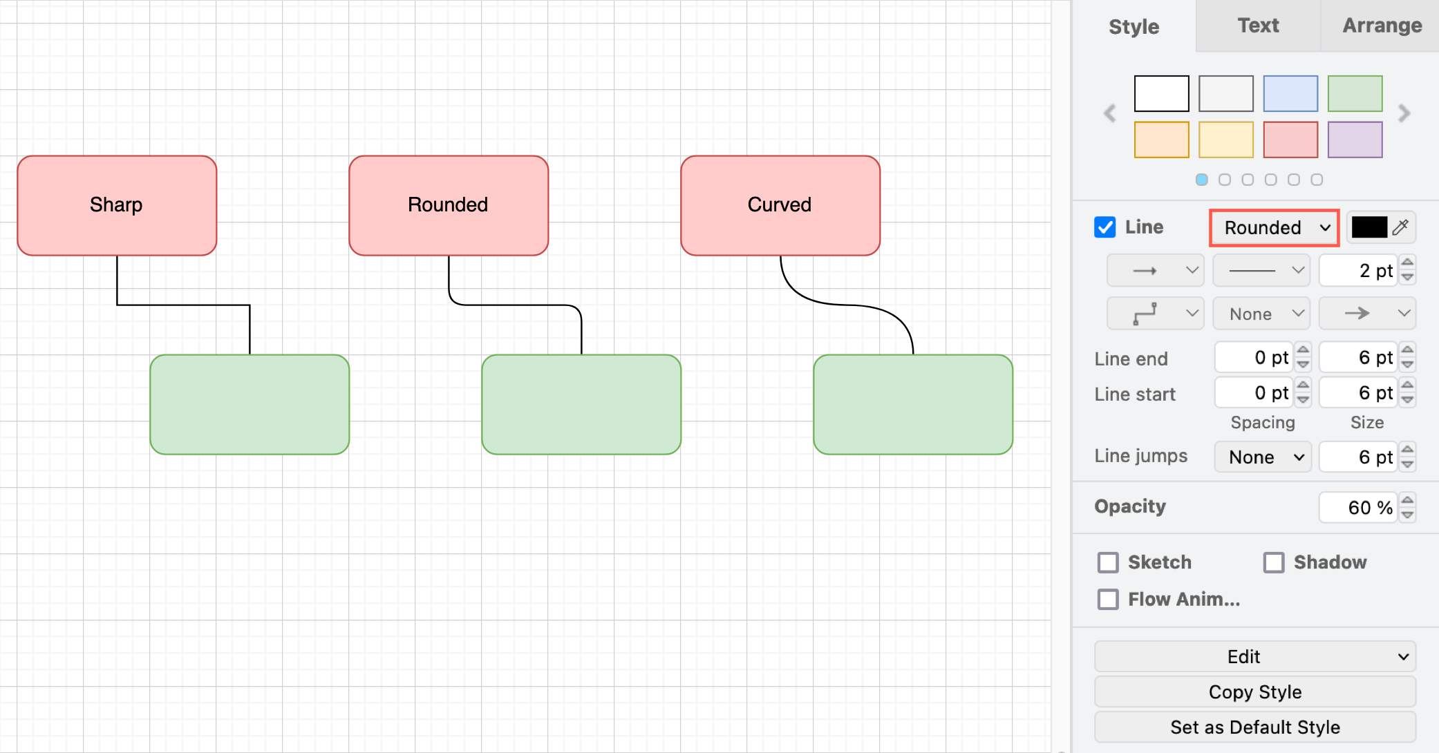
Rounded
Rounded corners mean we still use the polyline waypoints computed earlier, but replace sharp corners with smooth transitions at the joints. The steps are:
- Walk each bend in the polyline.
- On both sides of each corner, step back along the segment (by at most half the segment length).
- Use
quadTo(or an equivalent curve command) to draw a smooth fillet at the corner.
Quadratic Bezier
Use quadratic Bezier segments to connect adjacent control points:
const p0 = pts[n - 2];
const p1 = pts[n - 1];
parts.push(
    `Q ${formatNumber(p0.x)} ${formatNumber(p0.y)} ${formatNumber(
        p1.x,
    )} ${formatNumber(p1.y)}`,
);
Cubic Bezier
When there are 3n+1 points, interpret them directly as cubic Bezier control points in the form [anchor, cp1, cp2, anchor, ...]; otherwise fall back to quadratic Bezier segments.
if ((n - 1) % 3 === 0) {
    for (let i = 1; i + 2 < n; i += 3) {
        const cp1 = pts[i];
        const cp2 = pts[i + 1];
        const end = pts[i + 2];
        parts.push(
            `C ${formatNumber(cp1.x)} ${formatNumber(cp1.y)} ` +
                `${formatNumber(cp2.x)} ${formatNumber(cp2.y)} ` +
                `${formatNumber(end.x)} ${formatNumber(end.y)}`,
        );
    }
    return parts.join(' ');
}
[WIP] Export SVG
When exporting, it is no longer sufficient to save only geometric information; logical relationships must also be persisted. For example, draw.io saves the original mxfile content in the <svg> content attribute when exporting (this is not part of any formal spec):
<svg content='<mxfile host="app.diagrams.net" diagram name="Page-1"'></svg>We might also use:
<line x1="0" y1="0" data-binding="" />Editor
Highlight anchors
- When a node is selected, display available anchor points from which connections can be initiated.
- When an edge is selected, highlight dockable anchor points during dragging.