Lesson 21 - Transformer
In Lesson 14, we briefly introduced the "selection mode" in canvas mode. In this mode, after selecting a shape, an operation layer is overlaid on the shape, allowing it to be moved through drag behavior. In this lesson, we will provide more shape editing capabilities, including resize and rotation.
In Konva, the operation layer on selected shapes is called Transformer, which provides the following examples:
We also chose to use the name Transformer, which looks very similar to the shape's AABB. In fact, it's called OBB (oriented bounding box), which is a rectangle with a rotation angle under the world coordinate.
Serializing Transform Matrix and Dimension Information
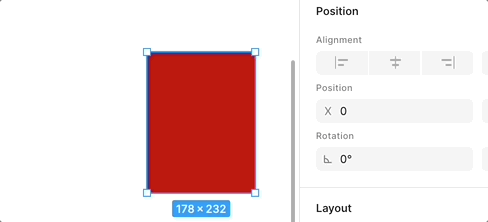
In Figma, the local transform matrix and dimension information for shapes are as follows. We know that for 2D shapes, the mat3 transform matrix can be decomposed into translation, scale, and rotation parts. Among them, X/Y corresponds to translation, and scale will be introduced in the flip section. fig-file-parser
Therefore, we chose to modify the SerializedNode structure to make it describe multiple shapes as much as possible, while removing some shape position attributes, such as cx/cy for Circle, since we can calculate cx/cy through x/y and width/height.
export interface TransformAttributes {
    // Transform
    x: number;
    y: number;
    rotation: number;
    scaleX: number;
    scaleY: number;
    // Dimension
    width: number;
    height: number;
}
<circle cx="100" cy="100" r="50" /> is serialized as follows, using ellipse to represent it for more flexible resizing in the future:
call(() => {
    const { createSVGElement, svgElementsToSerializedNodes } = ECS;
    const $circle = createSVGElement('circle');
    $circle.setAttribute('cx', '100');
    $circle.setAttribute('cy', '100');
    $circle.setAttribute('r', '50');
    const nodes = svgElementsToSerializedNodes([$circle]);
    return nodes[0];
});
For shapes like Polyline and Path that are defined through point and d attributes, we cannot delete these attributes. Instead, we need to calculate their AABB and recalculate these attributes. Taking <polyline points="50,50 100,100, 100,50" /> as an example:
call(() => {
    const { createSVGElement, svgElementsToSerializedNodes } = ECS;
    const $polyline = createSVGElement('polyline');
    $polyline.setAttribute('points', '50,50 100,100, 100,50');
    const nodes = svgElementsToSerializedNodes([$polyline]);
    return nodes[0];
});
Anchors
Transformer's anchors are divided into two categories: Resize and rotation, with two common combinations in terms of number.
One is adopted by Excalidraw and Konva, using 8 anchors around the perimeter for Resize, plus an independent rotation anchor:

The other is adopted by tldraw and Figma, using 4 anchors. When approaching these 4 anchors from the outside, it becomes rotation, while horizontal and vertical Resize is achieved by dragging the four edges:

We chose this seemingly more concise solution: a Rect mask as the parent node, and four child nodes Circle anchors:
const mask = this.commands.spawn(
    new UI(UIType.TRANSFORMER_MASK),
    new Transform(),
    new Renderable(),
    new Rect(), // Using Rect component
);
const tlAnchor = this.createAnchor(0, 0, AnchorName.TOP_LEFT); // Using Circle component
const trAnchor = this.createAnchor(width, 0, AnchorName.TOP_RIGHT);
const blAnchor = this.createAnchor(0, height, AnchorName.BOTTOM_LEFT);
const brAnchor = this.createAnchor(width, height, AnchorName.BOTTOM_RIGHT);

this.commands
    .entity(mask)
    .appendChild(this.commands.entity(tlAnchor))
    .appendChild(this.commands.entity(trAnchor))
    .appendChild(this.commands.entity(blAnchor))
    .appendChild(this.commands.entity(brAnchor));
Transformer Coordinate System
In Lesson 6 - Coordinate System Conversion, we implemented the conversion between Viewport, Canvas, and Client coordinate systems. Here we need to introduce a new coordinate system, the local coordinate system of the mask. For example, when the mask has transformations (such as rotation), the anchor points as child nodes need to know their position in the world coordinate system. We add this set of conversion methods:
transformer2Canvas(camera: Entity, point: IPointData) {
    const { mask } = camera.read(Transformable);
    const matrix = Mat3.toGLMat3(mask.read(GlobalTransform).matrix);
    const [x, y] = vec2.transformMat3(
      vec2.create(),
      [point.x, point.y],
      matrix,
    );
    return {
      x,
      y,
    };
}
canvas2Transformer(camera: Entity, point: IPointData) {}
Display CSS Cursor
When hovering over an anchor point, the mouse style needs to intuitively show the corresponding function, implemented by modifying the <canvas> style in the web end. The default CSS cursor has limited supported icons, for example, there is no icon for rotation semantics, and in Excalidraw and Konva, we can only use grab instead. Another example is that there are indeed 8 icons for Resize, but because shapes can be rotated, when the rotation angle is not an integer multiple of 45, even if we calculate and choose the appropriate icon like Konva does, we cannot accurately represent it:
function getCursor(anchorName: string, rad: number) {
    rad += DEG_TO_RAD * (ANGLES[anchorName] || 0);
    const angle = (((RAD_TO_DEG * rad) % 360) + 360) % 360;

    if (inRange(angle, 315 + 22.5, 360) || inRange(angle, 0, 22.5)) {
        return 'ns-resize';
    }
}
Therefore, we need to use custom mouse styles and be able to dynamically adjust based on rotation angle. How can I rotate a css cursor provides a way using SVG, and tldraw adds logic for dynamic angle calculation on this basis, see: useCursor. Taking the top-right anchor point as an example:
Apply the rotation transformation to the SVG icon to get the Cursor value at this time:
`url("data:image/svg+xml,<svg height='32' width='32'>...
    <g fill='none' transform='rotate(${
      r + tr // rotation angle
    } 16 16)>
And when the mouse gets closer to the anchor point, it changes from rotation to Resize interaction:
How to trigger picking when approaching the anchor point from far away?
Expand Hit Area
First, we thought of allowing shapes to expand or even customize the hit area, for example, Pixi.js provides hitArea. We can also add this field to the Renderable component:
export class Renderable {
    @field({ type: Type.object, default: null }) declare hitArea: Circle | Rect;
}
Consider this property when computing bounds in the ComputeBounds System, so we can set a circular detection area that's larger than the anchor point:
if (hitArea instanceof Circle) {
    renderBounds = Circle.getRenderBounds(hitArea);
}
But this approach has an obvious problem: even if we set the hit area to be 5 times larger than the anchor point, when the camera zooms, we still need to hover over the anchor point to trigger picking. Therefore, we need to consider picking outside the Canvas world coordinate system.
Picking in Viewport Coordinates
We need to perform picking detection in the Viewport coordinate system, so we can ignore camera zoom.
First, we need to calculate the positions of the four anchor points in the Canvas world coordinate system, rather than directly using the anchor points' cx/cy, otherwise it will go wrong when the Transformer itself has rotation (we'll see this soon):
hitTest(api: API, { x, y }: IPointData) {
    const { tlAnchor, trAnchor, blAnchor, brAnchor } = camera.read(Transformable);

    const { x: tlX, y: tlY } = api.canvas2Viewport(
        // Need to consider Transformer's own transformation, such as rotation
        api.transformer2Canvas(camera, {
            x: tlAnchor.read(Circle).cx,
            y: tlAnchor.read(Circle).cy,
        }),
    );
    // Omit calculation of other anchor positions

    const distanceToTL = distanceBetweenPoints(x, y, tlX, tlY);
}
Then first determine if the minimum distance to the four anchor points meets the threshold for Resize interaction, if it does, return the corresponding mouse style icon name, add the rotation angle to get the rotated SVG:
if (minDistanceToAnchors <= TRANSFORMER_ANCHOR_RESIZE_RADIUS) {
    if (minDistanceToAnchors === distanceToTL) {
        return {
            anchor: AnchorName.TOP_LEFT,
            cursor: 'nwse-resize',
        };
    }
}
Next, enter the rotation interaction detection. At this time, the detection point cannot be inside the Transformer, you can use the detection method introduced in Check if Point Is Inside A Polygon:
else if (
    !isInside &&
    minDistanceToAnchors <= TRANSFORMER_ANCHOR_ROTATE_RADIUS
) {
    if (minDistanceToAnchors === distanceToTL) {
        return {
            anchor: AnchorName.TOP_LEFT,
            cursor: 'nwse-rotate',
        };
    }
}
Finally, come to the Resize detection of the four edges of the Transformer, here we need to calculate the distance from the detection point to the line segment, refer to Gist - point to line 2d:
import distanceBetweenPointAndLineSegment from 'point-to-segment-2d';

const distanceToTopEdge = distanceBetweenPointAndLineSegment(
    point,
    [tlX, tlY],
    [trX, trY],
);
// Omit calculation of distance to other 3 edges

if (minDistanceToEdges <= TRANSFORMER_ANCHOR_RESIZE_RADIUS) {
    if (minDistanceToEdges === distanceToTopEdge) {
        return {
            anchor: AnchorName.TOP_CENTER,
            cursor: 'ns-resize',
        };
    }
}
Single Shape Resize
In Figma / FigJam, besides being able to freely change size by dragging the four corner anchor points and four edges, you can also:
- Press Option or Alt while dragging to scale from the geometric center
- Press Shift while dragging to fix the opposite corner/edge, scale proportionally along horizontal and vertical directions
- Combine these keys
The effect is as follows, from: Resize, rotate, and flip objects in FigJam
Let's first look at how to implement free size change. Taking the top-left anchor point as an example, when dragging, the bottom-right anchor point is fixed:
private handleSelectedResizing(
    api: API,
    canvasX: number,
    canvasY: number,
    anchorName: AnchorName,
) {
    const { x, y } = api.canvas2Transformer({
      x: canvasX,
      y: canvasY,
    });
    if (anchorName === AnchorName.TOP_LEFT) {
        // Set top-left anchor point position
        Object.assign(tlAnchor.write(Circle), {
            cx: x,
            cy: y,
        });
    }
    // Omit other anchor point handling logic
    {
        const { cx: tlCx, cy: tlCy } = tlAnchor.read(Circle);
        const { cx: brCx, cy: brCy } = brAnchor.read(Circle);
        const width = brCx - tlCx;
        const height = brCy - tlCy;
        const { x, y } = api.transformer2Canvas({ x: tlCx, y: tlCy });
        // Recalculate selected shape position and size
        this.fitSelected(api, {
            x,
            y,
            width,
            height,
            rotation: this.#rotation,
        });
    }
}
Finally, transform the selected shape based on the top-left and bottom-right anchor points.
Transform Shape
Now that we know the properties before and after resize (transform and dimension information), it's easy to calculate the transition matrix between these two states:
// @see https://github.com/konvajs/konva/blob/master/src/shapes/Transformer.ts#L1106

[delta transform] = [new transform] * [old transform inverted]const baseSize = 10000000;
const oldTr = mat3.create();
mat3.translate(oldTr, oldTr, [oldAttrs.x, oldAttrs.y]);
mat3.rotate(oldTr, oldTr, oldAttrs.rotation);
mat3.scale(oldTr, oldTr, [
oldAttrs.width / baseSize,
oldAttrs.height / baseSize,
]);
const newTr = mat3.create();
mat3.translate(newTr, newTr, [newAttrs.x, newAttrs.y]);
mat3.rotate(newTr, newTr, newAttrs.rotation);
mat3.scale(newTr, newTr, [
newAttrs.width / baseSize,
newAttrs.height / baseSize,
]);
const delta = mat3.multiply(newTr, newTr, mat3.invert(mat3.create(), oldTr));But we can't apply this matrix directly to the selected shape, we also need to consider the transformation of the parent node in the scene graph in the world coordinate system:
[delta transform] * [parent transform] * [old local transform] = [parent transform] * [new local transform]We can get the new transformation of selected shape in local coordinate system after left-multiplying its parent's world transform:
[new local] = [parent inverted] * [delta] * [parent] * [old local]Finally the new matrix under the local coordinate system is applied to the selected shape.
Lock Aspect Ratio
Still taking the top-left anchor point as an example, when locking the aspect ratio, we can't directly set its position. We need to recalculate the top-left anchor point's position based on the shape's aspect ratio at the start of dragging, while keeping the bottom-right anchor point position unchanged.
First, record the selected shape's OBB and aspect ratio when starting to drag the anchor point, equivalent to the diagonal slope:
if (input.pointerDownTrigger) {
    if (type === UIType.TRANSFORMER_ANCHOR) {
        this.#obb = this.getSelectedOBB();
        const { width, height } = this.#obb;
        const hypotenuse = Math.sqrt(Math.pow(width, 2) + Math.pow(height, 2));
        this.#sin = Math.abs(height / hypotenuse);
        this.#cos = Math.abs(width / hypotenuse);
    }
}
During dragging:
- Keep the bottom-right anchor point position unchanged
- Calculate the diagonal distance from top-left to bottom-right at this time
- Recalculate the top-left anchor point position based on the previously saved aspect ratio
if (lockAspectRatio) {
    // 1.
    const comparePoint = {
        x: brAnchor.read(Circle).cx,
        y: brAnchor.read(Circle).cy,
    };
    // 2.
    newHypotenuse = Math.sqrt(
        Math.pow(comparePoint.x - x, 2) + Math.pow(comparePoint.y - y, 2),
    );
    const { cx, cy } = tlAnchor.read(Circle);
    const reverseX = cx > comparePoint.x ? -1 : 1;
    const reverseY = cy > comparePoint.y ? -1 : 1;
    // 3.
    Object.assign(tlAnchor.write(Circle), {
        cx: comparePoint.x - newHypotenuse * this.#cos * reverseX,
        cy: comparePoint.y - newHypotenuse * this.#sin * reverseY,
    });
}
It's worth noting that Konva.js does not support dragging all four edges while preserving the aspect ratio. In such cases, you need to disable these four anchor points. For details, see: Is there a way to keep the image aspect ratio on transform?.
However, we can easily achieve this. Taking dragging the right edge anchor point as an example:
- First, set the X coordinate of the bottom-right anchor point
- Since the X coordinate of the top-left anchor point remains unchanged, the transformed width can be calculated
- With the aspect ratio locked, the transformed height is also determined, allowing calculation of the transformed height
- Based on the height difference before and after transformation, set the Y coordinates of the top-left and bottom-right anchor points
if (anchorName === AnchorName.MIDDLE_RIGHT) {
    // 1.
    brAnchor.write(Circle).cx = x;

    if (lockAspectRatio) {
        // 2.
        const newWidth = brAnchor.read(Circle).cx - tlAnchor.read(Circle).cx;
        const tan = sin / cos;
        const newHeight = newWidth * tan; // 3.
        const deltaY = newHeight - (prevBrAnchorY - prevTlAnchorY);
        // 4.
        brAnchor.write(Circle).cy = brAnchor.read(Circle).cy + deltaY / 2;
        tlAnchor.write(Circle).cy = tlAnchor.read(Circle).cy - deltaY / 2;
    }
}
During dragging, we can show the diagonal line in real-time to give users a clear hint (usually a dashed line).
Centered Scaling
Still taking the top-left anchor point as an example, at this time the fixed reference point changes from the bottom-right anchor point to the geometric center point, also recorded at the start of dragging:
const comparePoint = centeredScaling
    ? {
          x: this.#obb.width / 2,
          y: this.#obb.height / 2,
      }
    : {
          x: brAnchor.read(Circle).cx,
          y: brAnchor.read(Circle).cy,
      };
Then recalculate the bottom-right anchor point position, symmetrical to the top-left anchor point about the center point:
if (centeredScaling) {
const tlOffsetX = tlAnchor.read(Circle).cx - prevTlAnchorX;
const tlOffsetY = tlAnchor.read(Circle).cy - prevTlAnchorY;
Object.assign(brAnchor.write(Circle), {
cx: brAnchor.read(Circle).cx - tlOffsetX,
cy: brAnchor.read(Circle).cy - tlOffsetY,
});
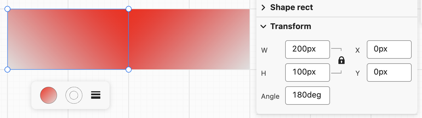
}Flip
When dragging an anchor point or edge to the opposite direction, flipping occurs. The following is the effect in Figma, note the change in Rotation:
We use a gradient background to show this flipping effect more clearly:
Rotation
Rotation in Figma:
Hover just outside one of the layer's bounds until the icon appears. Click and drag to rotate your selection: Drag clockwise to create a negative angle (towards -180° ). Drag counterclockwise to create a positive angle (towards 180° ) Hold down Shift to snap rotation values to increments of 15.
- First, compute the geometric center of the OBB, taking rotation into account.
- Then accumulate the rotation angle by taking the
atan2delta relative to the previous sample point, and normalize it to((-\pi,\pi])withatan2(sin, cos)to avoid discontinuities when crossing(\pm\pi). - On pointer down, initialize
rotateLastPointerAngleandrotateAccumulated = 0in canvas coordinates (with the same pixel-aligned snapping used by move logic). Keep the center fixed. When only changing rotation, usealignObbOriginToFixedCenterto derive the newx/yso the center stays at(px, py), then call the existingfitSelectedto reuse the same Konva-style delta transform pipeline as resize.
// 1.
const [px, py] = this.obbWorldCenter(selection.obb);
// 2.
const cur = Math.atan2(canvasY - py, canvasX - px);
let delta = cur - selection.rotateLastPointerAngle;
delta = Math.atan2(Math.sin(delta), Math.cos(delta));
selection.rotateLastPointerAngle = cur;
selection.rotateAccumulated += delta;
// 3.
const newRotation = selection.obb.rotation + selection.rotateAccumulated;
const newAttrs = this.alignObbOriginToFixedCenter(
    selection.obb,
    px,
    py,
    newRotation,
);
this.fitSelected(api, newAttrs, selection);
Change the Rotation Origin
The following is the effect of Figma's Change the rotation origin:
Implementation notes:
- Add a center anchor (
AnchorName.CENTER) to the transformer mask. This anchor is draggable. - Store the custom rotation origin in transformer-local coordinates (
rotatePivotX/Y) and mark whether it is user-pinned (rotatePivotPinned). - On pointer move while dragging the center anchor, convert canvas coordinates into transformer-local coordinates:
const { x, y } = api.canvas2Transformer({ x: canvasX, y: canvasY }, mask);
tf.rotatePivotX = x;
tf.rotatePivotY = y;
tf.rotatePivotPinned = true;- During rotation, use this pivot (fall back to geometric center if unset), then keep the pivot's world position fixed while solving new OBB origin:
const [px, py] = this.getRotatePivotWorld(api, selection);
const pivotLocalX = Number.isNaN(tf.rotatePivotX)
    ? selection.obb.width / 2
    : tf.rotatePivotX;
const pivotLocalY = Number.isNaN(tf.rotatePivotY)
    ? selection.obb.height / 2
    : tf.rotatePivotY;

const newAttrs = this.alignObbOriginToFixedPivot(
    selection.obb,
    pivotLocalX,
    pivotLocalY,
    px,
    py,
    newRotation,
);- Reset pivot to center when the selected node set changes.
Move Shapes with Arrow Keys
Figma provides the Nudge layers feature, allowing you to move shapes using the up, down, left, and right arrow keys, and you can also use Shift for larger movements. In our implementation, we'll use fixed distances:
if (e.key === 'ArrowUp') {
    e.preventDefault();
    this.api.updateNodeOBB(selected, { y: selected.y - 10 });
    this.api.record();
}
Transformer for other shapes
The transformer we have implemented so far is suitable for shapes such as circles, ellipses, and rectangles, but it is not suitable for straight lines, polyline segments, or piecewise curves, which require more control points.
Transformer for line
Finally, a straight line requires only two anchor points, allowing the series of operations based on the bounding rectangle we previously introduced to be significantly simplified.
export class Transformable {
    @field.ref declare lineMask: Entity;
    @field.ref declare x1y1Anchor: Entity;
    @field.ref declare x2y2Anchor: Entity;
}
Transformer for polyline
For a polyline, each connection point has a corresponding control point, and an additional point is inserted between each pair of adjacent control points to generate a new line segment:
export class Transformable {
    @field.ref declare polylineMask: Entity;
    @field.object declare controlPoints: Entity[];
    @field.object declare segmentMidpoints: Entity[];
}
The corresponding interaction is that when you hover over a control point, you can press the Delete key to delete it. To accommodate both the rectangular Transformer's resize and rotate behavior and vertex editing, we also support double-clicking to enter control point editing mode.
Path
tldraw provides an example: cubic-bezier-shape. For interactive editing, two problems need to be solved:
- Stable editable points: every anchor and every Bézier control point can be selected and dragged, and changes are written back to
d. - Round-trip without losing semantics: use a small, predictable set of command types where possible, and avoid hand-rolling a full path parser in the editor.
So we normalize d into a small vocabulary of commands (e.g. convert relative commands to absolute), then use command index + coordinate offset in the array as each handle’s identity. While dragging, only numeric coordinates change; finally path2String serializes back to a string.
| Command | Handles produced | meta meaning |
|---|---|---|
| M / L | One vertex | coordOffset: 1 → that point (x, y) |
| Q | Control + end | offsets 1 and 3 |
| C | cp1, cp2, end | offsets 1, 3, 5 |
| A | End point only | offset 6 (arcs have no Bézier handles in this editor; only the endpoint is exposed) |
interface PathControlHandleMeta {
    commandIndex: number; // Index in the normalized command array.
    coordOffset: number; // Start index of this handle’s coordinates (1-based, since `command[0]` is the command letter).
}

type HandlePoint = {
    x: number;
    y: number;
    meta: PathControlHandleMeta;
};
Similarly, double-click to enter control point editing mode.